Those Who dont have the courage to leave the shore never find the land

The pneumatic boot is a rubber device attached to a wing's leading edge, invented by the Goodrich Corporation (previously known as B.F. Goodrich) in 1923. Portions of the boot are inflated to break ice off of the boot, de-icing the wing. Rubber boots are used on jets and propeller driven aircraft.
A bleed air system is used by jet aircraft to keep flight surfaces above the freezing temperature required for ice to accumulate (called anti-icing). The hot air is "Bled" off of the jet engine into tubes routed through wings, tail surfaces, and engine inlets.
Electrical thermal systems use electricity to heat the protected surface. The electric heaters are usually flexible enough to use as anti-icers or de-icers. As a de-icer, the heater melts the ice, the ice no longer sticks to the surface due to aerodynamic forces. As an anti-icer, the heater keeps the surface to the point that the ice does not form.
Electro-mechanical systems use a mechanical force to knock the ice off of the flight surface. Typically, actuators are installed underneath the skin of the structure. The actuator is moved to induce a shock wave in the protected surface to dislodge the ice.
A weeping wing system uses a liquid (such as ethylene glycol) to coat the surface and prevent ice from accumulating.
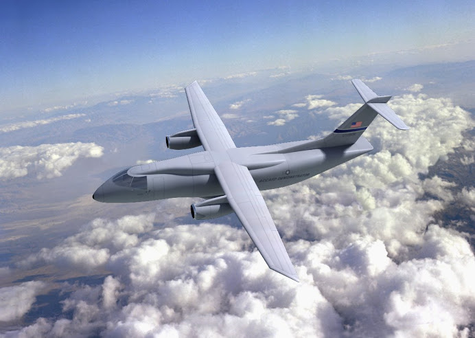
Ice accumulates on the leading edge of wings, tails, and horizonal stabilizers as an aircraft flies through a cloud containing super-cooled water droplets. Ice forms because super-cooled water droplets in clouds contact the aircraft. This contact imparts energy into the droplet and causes it to change from liquid water to solid water (ice). As the ice layer grows (accretes), it affects the airflow over the affected surface. If the layer grows large enough, it can create lift or handling problems for the aircraft.
Ice can also accumulate on helicopter rotor blades and aircraft propellers. The accretion causes weight and aerodynamic imbalances that are amplified due to the rapid rotation of the propeller or rotor.
Ice accreting on the leading edge (lip) of engine inlets causes flow problems and can lead to ice ingestion. In turbofan engines, laminar airflow is required at the face of the fan. Because of this, most engine ice protection systems are anti-ice systems (prevent build up).
Goodrich Corporation (formerly B.F. Goodrich), De-icing and Specialty Systems (DSSD)
Cox Aerospace
Kelly Aerospace, Thermal Systems Division
Ice Management Systems
Hutchinson Aerospace
Meggitt Thermal Systems
 De-icing is the process of removing ice from a surface.
Anti-icing is the process of preventing ice from forming on a surface.
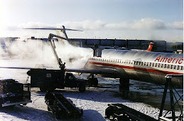
De-icing can be accomplished by mechanical methods (scraping), through the application of heat, by use of chemicals designed to lower the freezing point of water (various salts or alcohols), or a combination of these different techniques.When there are freezing conditions and precipitation, it is critical that an aircraft be de-iced. Failure to do so means the surface of the aircraft's wings will be too rough to provide for the smooth flow of air and thereby greatly degrading the ability of the wing to generate lift, possibly resulting in a crash. If large pieces of ice separate once the aircraft is in motion, they can be ingested into turbine engines or impact moving propellers and cause catastrophic failure. Thick ice can also lock up the control surfaces and prevent them from moving properly. Because of this potentially severe consequence, de-icing is performed at airports where temperatures are likely to dip below the freezing point.De-icing techniques are also employed to ensure that engine inlets and various sensors on the outside of the aircraft are clear of contamination caused by ice or snow.De-icing on the ground is usually done by spraying aircraft with a deicing fluid such as monopropylene glycol, similar to the toxic ethylene glycol antifreeze used in some automobile engine coolants. Ethylene glycol is still in use for aircraft deicing in some parts of the world, but Monopropylene glycol is more common due to the fact that it is classified as non-toxic, unlike ethylene glycol. Nevertheless, it still must be used with a containment system to capture all of the used liquid, so that it cannot seep into the ground and streams. Even if it is classified as non-toxic, it still has negative effects in nature, as it uses oxygen as it breaks down, causing other life to suffocate. (In one case, a significant snow in Atlanta in early January 2002 caused an overflow of such a system, briefly contaminating the Flint River downstream of the Atlanta airport.) Many airports successfully recycle used deicing fluid, separating out water and solid contaminants in order to be able to reuse the fluid.Though there are several different formulations of deicing fluid, they fall into two basic categories: Heated glycol diluted with water for deicing and snow/frost removal, also referred to as "Newtonian fluids", and unheated, undiluted glycol that has been thickened (imagine half-set gelatin), also referred to as "Non-Newtonian fluids", that is applied as an agent to retard the future development of ice or to prevent falling snow or sleet from accumulating. In some cases both types of fluid are applied, first the heated glycol/water mixture to remove contaminants, followed by the unheated thickened fluid to keep ice from reforming before the aircraft takes off. This is referred to as "a two-step procedure".Inflight ice buildups are most frequent on the leading edges of the wings, tail and engines (including the propellors or fan blades). Lower speed aircraft frequently use pneumatic boots on the leading edges of wings and tail to affect de-icing in flight. The rubber coverings are periodically inflated, causing ice to crack and flake off in the slipstream. Once the system is activated by the pilot, the inflation/deflation cycle is automatically controlled. In the past, it was thought such systems can be defeated if they are inflated too soon; that the pilot must allow a fairly thick layer of ice to form before inflating the boots. More recent research shows “bridging” does not occur with any modern boots (ref: http://www.aopa.org/asf/publications/sa11.pdf).Some aircraft may also use electrically heated resistive elements embedded in a rubber sheet cemented to the leading edges of wings and tail surfaces, propeller leading edges, and helicopter rotor blade leading edges. Such systems usually operate continuously. When ice is detected, they first function as de-icing systems, then as anti-icing systems for the duration of flight in icing conditions. Some aircraft use chemical de-icing systems which pump antifreeze such as alcohol or propylene glycol through small holes in the wing surfaces and at the roots of propeller blades, causing the ice to melt and making the surface inhospitable to further ice formation. A fourth system, developed by the National Aeronautics and Space Administration, detects ice on the surface by sensing a change in resonance frequency. Once an electronic control module has determined that ice has formed, a large current spike is pumped into the transducers to generate a sharp mechanical shock, cracking the ice layer and causing it to be peeled off by the slipstream.Many modern civil fixed-wing transport aircraft use anti-ice systems on the leading edge of wings, engine inlets and air data probes using warm air. This is bled off the powerplants and is ducted into a cavity just under the surface to be anti-iced. The warm air heats the surface up to a few degrees above zero, preventing ice from forming on that surface. The system may operate completely autonomously, switching itself on and off as the aircraft enters and leaves icing conditions.
Infrared is the transmission of energy by means of electromagnetic waves or rays. Infrared is invisible and travels at the speed of light in straight lines from the heat source (the emitter) to all surfaces and objects (the receivers) without significantly heating the space (air) through which they pass. When infrared waves strike an object, they release their energy as heat. This heat is then either absorbed or reflected by the cooler surface. Infrared energy is continually exchanged between "hot" and "cold" surfaces until all surfaces have reached the same temperature (equilibrium). The colder the surfaces, the more effective the infrared transfer from the emitter. This heat transfer mechanism is substantially faster than conventional heat transfer modes used by conventional deicing (convection and conduction) due to the cooling effect of the air on the deicing fluid spray.The benefit of Infrared Aircraft Deicing is the dramatic reduction in traditional fluid deicing methods, which pose environmental contamination risks and require extensive and expensive collecting methods. With Infrared Deicing, an aircraft can simple taxi through an infrared-equipped hanger near gates. Deicing occurs in less time than required by conventional means, which means a reduction of both costs to the airlines and delay times for passengers. The drawback is the high energy consumption, which reduces the environmental benefits.One of the market leaders in Infrared Deicing is a Canadian company known as Radiant Energy Corp. They have implemented various facilities in Norway and New York's JFK airport, and recently have come under contract to supply infrared deicing across the state of Alaska. More information can be found at Radiant Energy's Website [1]
De-icing of roads has traditionally been done with salt, spread by snowplows or other dump trucks designed to spread it, along with sand and gravel, on slick roads. Sodium chloride (rock salt) is normally used, as it is inexpensive and readily available in large quantities. However, since salt water still freezes at -18°C or 0°F, it is of no help when the temperature falls below this point. It also has a strong tendency to cause corrosion, rusting the steel used in most vehicles and the rebar used in concrete bridges. More recent snowmelters use other salts, such as calcium chloride and magnesium chloride, which not only depress the freezing point of water to a much lower temperature, but also produce an exothermic reaction. They are somewhat safer for concrete sidewalks, but excess should still be removed.More recently, organic compounds have been developed that reduce the environmental issues connected with salts and have longer residual effects when spread on roadways, usually in conjunction with salt brines or solids. These compounds are generated as byproducts of agricultural operations such as sugar beet refining or the distillation process that produces ethanol.[2]Since the 1990s, use of liquid chemical melters has been increasing, being sprayed on roads by nozzles instead of a spinning spreader. Liquid melters are more effective at preventing the ice from bonding to the surface than melting through existing ice.In Nagano, Japan, relatively inexpensive hot water bubbles up through holes in the pavement to melt snow, though this solution is only practical within a city or town. Some individual buildings may melt snow and ice with electric heating elements buried in the pavement, or even on a roof to prevent ice dams under the shingles, or to keep massive chunks of snow and dangerous icicles from collapsing on anyone below. Small areas of pavement can be kept ice-free by circulating heated liquids in embedded piping systems.
 How Clouds Form: Clouds form when water vapor (water that has evaporated from the surface of the Earth) condenses (turns into liquid water or solid ice) onto microscopic dust particles (or other tiny particles) floating in the air. This condensation (cloud formation) happens when warm and cold air meet, when warm air rises up the side of a mountain and cools as it rises, and when warm air flows over a colder area, like a cool body of water. This occurs because cool air can hold less water vapor than warm air, and excess water condenses into either liquid or ice. For more on the water cycle, click here.
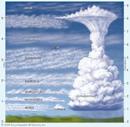
Types of Clouds:

Nimbo (meaning "rain") as a prefix, or nimbus added as a suffix, in a cloud name indicates that the cloud can produce precipitation (rain, snow, or other forms of falling water). Cumulo (meaning "heap") refers to piled-up clouds. Strato (meaning "layer") refers to flat, wide, layered clouds.
| Type of Cloud (Genus) | Abbreviation | Appearance | Composition | Altitude (height) |
|---|---|---|---|---|
| Cumulo-nimbus =Thunderheads | Sb | Can cause lightning, thunder, hail, strong rains, strong winds, and tornadoes | Near ground up to 75,000 feet (Vertical clouds) | |
| Cirro-stratus | Cs | Thin, wispy, appears in sheets. Located above thunderheads | Above 18,000 feet (High-altitude clouds) | |
| Cirrus | Ci | Thin, wispy, filamentous, or curly | Mostly composed of ice crystals | Above 18,000 feet (High-altitude clouds) |
| Cirro-cumulus | Cc | Small, puffy, patchy and/or with a wavelike appearance | Above 18,000 feet (High-altitude clouds) | |
| Alto-cumulus | Ac | Medium-sized puffy, patchy, scattered clouds - often in linear bands | 6,500 - 20,000 feet (Middle-altitude clouds) | |
| Alto-stratus | As | Thin, uniform | 6,500 - 20,000 feet (Middle-Alttude clouds) | |
| Strato-cumulus | Sc | Broad and flat on the bottom, puffy on top, | Below 6,500 feet (Low-altitude clouds) | |
| Cumulus | Cu | Puffy and piled up. | Below 6,500 feet (Vertical clouds) | |
| Stratus | St | Uniform, flat, thick to thin layered clouds will ill-defined edges | Mostly composed of liquid droplets | Below 6,500 feet (Low-altitude clouds) |
| Nimbo-stratus | Ns | Uniform, dark, flat, low, featureless clouds that produce precipitation | Mostly composed of liquid droplets | Below 6,500 feet (Low-altitude clouds) |
| Fog | Very low stratus clouds | Mostly composed of liquid droplets | In contact with the gound (Ground-hugging clouds) |
Other types of clouds:
Mammatus clouds are dark clouds shaped like sagging pouches. These clouds often appear after a tornado.
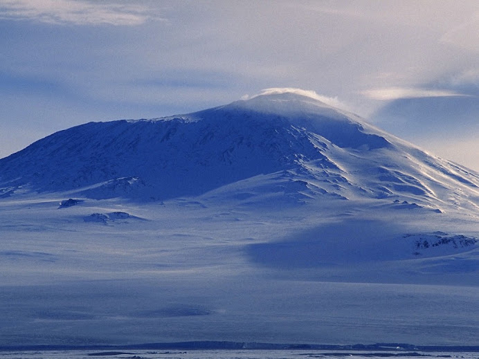
Orographic clouds are clouds that are formed as moist air rises over mountains or other major geographic features. The air floats up the side of the mountain and cools quickly, condensing and turning into a cloud.
A pileus cloud is a smooth cloud that is found over or on the top of a major geographic feature, like a mountain.
A contrail (short for CONdensation TRAIL) is a cloud-like vapor trail that forms behind some aircraft when flying in cold, clear, humid air. The contrail forms from the water vapor contained in the jet's engine exhaust.
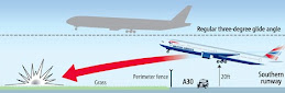
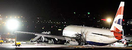
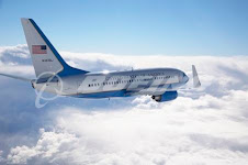
 A China Airlines (CAL) Boeing 737-800 nearly ran off the end of a runway on takeoff in southern Japan on 5 October.
 There was no damage to the aircraft as a result of the takeoff and no passengers were on board because it was on a ferry flight back to Taiwan, he adds.
Industrial Visit – Report Dated, January 08, 2008
Structural Engineering Research Centre – Chennai
Purpose of the Visit:
To get a clear idea about the researches those are carried on the field of
· Wind Testing
· Fatigue Testing
· Seismic Effect Testing
So let we see in detail about the places we visited.
Wind Tunnel Testing:
TECHNICAL DATA
( Boundary Layer Wind Tunnel )
Type : Open ground Blower type
Variable Speed : 0.5 m/s to 55 m/s
Fan : axial flow
Power rating for fan motor assembly : 600 HP
Test Section : 1.8 m x 2.5 m ( H x B )
Construction Ratio : 1.5
Exit velocity : 11 m/s (Max)
( Adjustable ceiling )
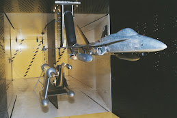
 We understood the clear function of the wind tunnel which is totally different from the wind tunnel that is placed in our college lab. We directly watched the functions of it. They are testing an antenna (weather) model which is going to be placed in Pune, the time we went there. Also we saw a lot of models that has been tested there. We got the clear idea on how the model is prepared and also how it is made based on the purpose. ( Pressure analyzing or flow visualization ). We saw that the models are prepared in a reduced size such that it will fix in the test section. We also witnessed the calculations that are taking place around the huge wind tunnel with the help of computers and manual calculations.
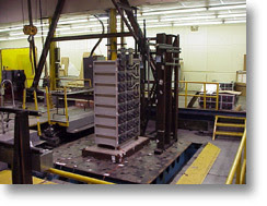
Fatigue Testing :
 In fatigue testing laboratory we saw the huge hydraulic jack which supplies 1000 KN on the material we place. Generally they place railway tracks, power plant pipe components, steel pipes, sewage sections which are made of either stainless steel or carbon steel. The company initially made the components with nil defects. After they make some initial cracks and they are testing the consistency by applying the load 2 million times cyclically. We got a clear idea on the cycles they applied. With the help of ACPD ( Alternate Current Potential Difference ) they monitor the crack development and the process. Thus they analyze the failur
e nature of the material under different load condition.
Seismic Testing Laboratory:

The structures which are going to be constructed are built in a reduced size and they apply the lateral loads on it. With the help of strain gauge technique they analyze the damage level and prepare a solution to damp that. They also have a stimulator section which is 4 m x 4m (Around three) to test the structures in different seismic level (that is to say in rector). They collected the three dimensional data from various geographical institute which have the large data of earthquake details. They feed it in the computer and later with the help of the actuators they stimulate the same quake level and analyze the damage. They are also testing the dampers placed in the structure (elasto-plastic dampers) and also the damping fluids (Magneto Realogical Fluid) which change its viscosity according to the vibrations. Even we had a nice question se
ssion with the chief in the seismic laboratory. He cleared a lot of doubts from the students.
Conclusion:
Thus we have completed our visit in a very useful manner.
 Marvelous Leap Of Mankind:
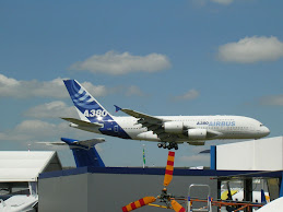
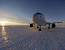
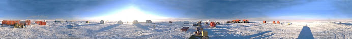
A passenger jet has made a historic landing on a new blue ice runway in Australia's Antarctic territory and regular flights are expected to start within a week, officials said Wednesday.
But trips on the Airbus A319 to the Wilkins Runway will be for scientists and research staff only, with no plans to open the airlink to tourists, project manager Charlton Clark told AFP.
The runway is four kilometres (2.5 miles) long, 700 metres thick and moves about 12 metres southwest a year because of glacial drift.
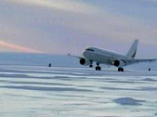
In the first trial landing on Monday, the plane pulled up within 1,000 metres despite the lack of friction to grab the wheels on the ice.
Clark said work had begun on the 10 million dollar (8.7 million US) runway 70 kilometres from Australia's Casey research station in 2005, with crews living in shipping containers.
"Just living in that environment, with conditions of minus 35 degrees and up to a hundred knots of wind, let alone doing the work, was an amazing undertaking," he said.
Using laser levelling technology, they graded and shaved the ice flat and must keep grooming it to keep it snow free.
The runway was named for the adventurer and aviator Sir Hubert Wilkins, who made the first flight in Antarctica 79 years ago.
Scientists and specialists working at Australia's Antarctic field stations, who previously had to spend weeks voyaging to and from the ice by sea, are expected to start flying within a week, he said.
Other nations with Antarctic research stations have been flying to the icy continent for years from countries such as New Zealand and South Africa, but using military aircraft.
The Australian Antarctic Division says its introduction of a modern jet aircraft, which can complete a return journey without refuelling, marks the start of a new era.
Charlton Clark(L), manager of the Antarctic Airlink Project, and Dr Jeremy Smith, Casey station leader, stand by the first Airbus A319 passenger jet to land in Antarctica on the purpose-built Wilkins glacial runway, around 70kms from the Australian Antarctic research station of Casey. Regular flights are expected to start within a week.
The first Airbus A319 passenger jet arrives at the purpose-built Wilkins glacial runway, around 70kms from the Australian Antarctic research station of Casey. Regular flights are expected to start within a week.
 Australia has scored an Antarctic coup by successfully landing a commercial airliner at its polar base.